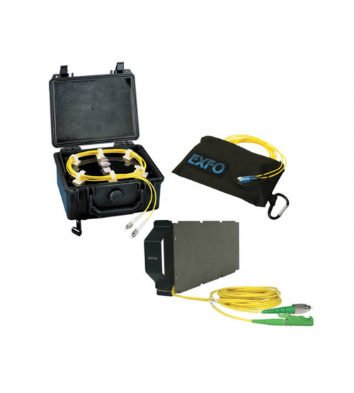
SPSB -lanuch cables
FTB-LTC/PSB/SPSB - launch test cable/pulse suppressor box
Used in conjunction with an OTDR, the FTB-LTC/PSB/SPSB covers the OTDR's dead zone, enabling loss measurement on the first and last connections of a fiber under test.
Description
Choice of configurations
Typically, the length of an OTDR’s dead zone is equivalent to that of the optical pulse plus a few meters. The chosen launch test cable should therefore be longer than the pulse dead zone used for the tests. For instance, a 1 µs pulse is approximately 100 m long; selecting a 150 m SPSB or a 300 m LTC/PSB would therefore be appropriate.
EXFO offers three types of launch cables:
The FTB-LTC module combines with an FTB-7000 series OTDR module in the FTB-500 or FTB-200 platform
The stand-alone PSB comes in a rugged, compact carrying case
The portable SPSB comes in a soft, easy-to-carry-everywhere pouch
How it works
Link characterization is often performed using an OTDR. But even though an OTDR has the shortest dead zones, because of the way loss is measured in a link, it does not allow the characterization of the first and last connectors without using a launch test cable, also called a pulse suppressor box. Here’s why.
The loss value associated with an event is the difference between the backscattering levels measured before and after the event. To account for the OTDR’s dead zone, obtaining a backscattering level before the first connector requires inserting a certain length of fiber between the OTDR port and the first connector of the fiber under test. At the other end of the link, the same length of fiber is added after the last connector of the “receive” cable.
In order to obtain an accurate, complete picture of the system’s loss—which is a critical aspect of fiber commissioning—a launch test cable should always be used at both ends of the fiber link.


