


Fluke 125 ScopeMeter® Oscilloscopes
ScopeMeter® 125: All the power of the 120-Series plus Industrial Bus Health Test capabilities and advanced power measurements on top
The compact ScopeMeter® is the rugged solution for industrial troubleshooting and installation applications. It’s a truly integrated test tool, with oscilloscope, multimeter and 'paperless' recorder in one affordable, easy-to-use instrument. Find fast answers to problems in machinery, instrumentation, control and power systems. Based on the Fluke 120 series, the 125 has all the capabilities of the 124 ScopeMeter extended with the capability to measure and analyze the signal quality on the common industrial buses
- Dual-input 40 MHz or 20 MHz digital oscilloscope
- Two 5,000 counts true-RMS digital multimeters
- Automatic measurements
- A dual-input TrendPlot™ recorder
- Connect-and-View™ trigger simplicity for hands-off operation
- Shielded test leads for oscilloscope, voltage, resistance and continuity measurements
- 10:1 Voltage Probe for high frequency measurements
- Up to 7 hours battery operation
- 600 V CAT III safety certified
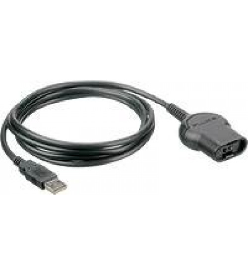
- Optically-isolated interface for PC connection
- Gives bus health and power measurements
In today’s complex systems, a meter measurement just doesn’t give enough detail to determine the cause of a fault. Signal anomalies, dropouts and glitches that might cause a machine to go down, are best displayed with an oscilloscope. The ScopeMeter 125 meets today’s need of simultaneously measuring and checking waveforms. The unique Connect-and-View™ triggering automatically displays stable waveforms of virtually any signal. It really is as easy as one-two-three!
A three-in-one tool

Dual-input measurement shows both meter reading and waveform at the same time today’s need of simultaneouslyThe ScopeMeter 125 combines a 40 or 20 MHz dual input digital storage oscilloscope, two true-RMS digital multimeters and a dual input TrendPlot™ recorder all in a compact, battery powered instrument. Leave all other test tools behind, the ScopeMeter 125 is the only tool you’ll need.
One test lead measures all

Check the starting capacitor of a motor using the ScopeMeter 125High frequency waveform-, meter-, capacitance- and resistance-measurements as well as continuity checks are all covered by the shielded test leads. No time wasted finding or swapping leads. The included accessories allow hook-up at test objects of every dimension.
The confidence to do a better job

Open the measure menu and select from 26 scope- and meter-measurementsWorking under time pressure and in cramped or difficult to reach locations means you want to focus on the job at hand, not on the test tool in your hand. Which is why the ScopeMeter 125 has Connect-and-View automatic triggering. You don’t have to worry about triggering and instrument settings, and you have all the information on screen to do the job right.
Battery powered mobility
Up to seven hours of battery operation frees you from mains outlets for true on-the-move working. The handheld format and the weight of just 1.2 kg, make the instrument easy to carry and to fit comfortably in your hand. The rugged and drip proof case assures long life and reliable operation in the harshest industrial environments.
Floating measurements, safety certified
While conventional oscilloscopes can only make measurements referenced to power line ground, the Fluke ScopeMeter 125 makes floating measurements so there is no risk of an accidental ground short circuit when making a connection. The ScopeMeter 125 and the included shielded test leads are safety certified for measurements on 600 V CAT III industrial power systems. And using the VPS40 probe, measurements up to 1000 V CAT II re fully supported! Via the optically isolated RS-232 or USB interface, the ScopeMeter 125 can be safely connected to a printer for direct print-out or to a PC for later analysis and documentation using FlukeView software.
Connect-and-View™ triggering for an instant, stable display

Connect-and-View captures even the most complex motor drive signalsScope users know how difficult triggering can be. Wrong settings show unstable and sometimes wrong results. Fluke’s unique Connect-and-View recognizes signal patterns, and automatically sets up correct triggering. It provides a stable, reliable and repeatable display of virtually any signal – including motor drive and control signals – without you touching a button. Signal changes are instantly recognized and settings adjusted for a stable display. Benefit from the speed and convenience when measuring a number of test points in quick succession.
Use TrendPlot™ to help find intermittents, fast

Cursors and zoom help you analyze the captured TrendPlotThe toughest faults to find are those that happen only once in a while: intermittents. They can be caused by bad connections, dust, dirt, corrosion or simply broken wiring or connectors. You may not be around to see it – your Fluke ScopeMeter test tool will. In this “paperless” recorder mode, you can plot the minimum and maximum peak values and average over time – up to 16 days. The two inputs can plot any combination of volts, amps, temperature, frequency and phase – with time and date stamp – to help lead you to the cause of those faults quickly.
Based on the Fluke 124, the Fluke 125 offers additional test capabilities for measurements on industrial machinery and industrial buses.
Furthermore, the Fluke 125 offers the following additional capabilities for tests on industrial machinery:
- Power Measurements for single phase and balanced 3-phase systems. The Fluke 125 can directly present you the Total Power (Watts), Apparent Power (VA), Reactive Power (VAR) and the Power Factor (PF), over a wide range of applied frequencies, including those seen with motor drives and inverters. As a result, you are able to easily see the effects on the various power measurements during start-up or under changing operational conditions. A current clamp is included as a standard.
- Harmonics mode graphically displays harmonics up to the 33rd harmonic to assist in fault-finding, e.g. with large non-linear loads.
- RPM and Hz reading for use with electrical and combustion engines.
- Vac pwm for use on motor drive outputs, reading the true output voltage experienced by the motor itself.
- Low impedance measurements giving a 0.01 ohms resolution for motor windings and the like.
FlukeView® Software for documenting, archiving and analysis

FlukeView® for Windows® helps you get more out of your ScopeMeter test tool by:
- Documenting – transfer waveforms, screens and measurement data to a PC. Print or import the data into your report.
- Add user text to individual ScopeMeter test tool settings – providing guidance to the operator when recalling a set-up.
- Archiving – create a library of waveforms with your comments for easy reference and comparison. Store complete Replay cycles for analysis of waveform changes. Store complete memory content of the ScopeMeter instrument on your PC for back-up purposes.
- Waveform Compare – store reference waveforms on the PC, or send a reference back to the ScopeMeter test tool for waveform comparison and “Pass/Fail” testing.
- Analysis – use cursors, perform spectrum analysis or export data to other analysis programs. ScopeMeter test tools are connected to a PC via an optically-isolated RS-232 or USB interface cable.

Additional features of the Fluke 125
The Fluke 125 is based on the Fluke 124 and includes all the functions and capabilities of that instrument. On top, a Bus Health Test mode allows for an analysis of the signal quality on industrial buses and networks, comparing measured signals to the standards’ signal requirements.
This section presents the Bus Health Test capabilities of the Fluke 125 specifically.
Fluke 125 is the portable oscilloscope of choice for the maintenance engineer who deals with industrial machinery and the industrial network connecting his machinery the like.

The Fluke 125 has all the functionality of the Fluke 124 plus it comes with the following extensions: Bus Health mode gives a clear “Good” / “Weak” / “Bad” indication for the electrical signals on industrial buses and networks, such as CAN-bus, Profi-bus, RS-232 and many more. The Fluke 125 validates the quality of the electrical signals as soon as any electrical signals are passed along the network. It checks the signal levels and speed, transition times and distortion, and compares these to the appropriate standards to help you find errors like improper cable connections and terminators. It helps you find the source of error in case communication comes to a halt. All the commonly found industrial network types are supported!
The Fluke 125 also offers advanced power measurements for single phase and balanced 3-phase systems, a Harmonics Mode and more.
Specifications Oscilloscope bandwidth 40 MHz Dual input true RMS meter VDC, VAC, VAC + VDC, Ohms,Continuity, Diode-test Current, °C, °F, Capacitance, dBV, dBM, Crest Factor, Touch Hold and Zeroset TrendPlot recording Automatic vertical scaling and time compression
Display the actual, MIN, MAX and AVG readingCursors Fluke 125/124: ∆T, 1/∆T, V, ∆V, rise- and fall time Sample rate 2.5 GS/s repetitive sampling
25 MS/s single shot samplingInputs and digitizers 2 Timebase range 20 ns - 1 min/div Input sensitivity 5 mV - 500 V/div Trigger types Connect-and-View™, Free Run, Single Shot, Edge, Video, External Glitch capture 40 ns Scope measurements Automatic measurements: 26 (all instruments) On top, Fluke 125 has additional measurement functions for Power (W), VA, VAR and Power Factor (PF) for single phase and balanced-three-phase (delta) power systems Harmonics mode Capability to analyze the harmonics contents of power signals
(see Harmonics Mode Section below for details)Maximum record length 512 min/max pts per input Memory 20 screens and setups Additional Power Measurement Capabilities Measurement types - Watt,
- VA
- VAR,
- Power Factor (PF)
Power configuration Single phase or balanced three-phase (delta-configuration) mains supply Voltage measurement Channel A; using STL120, voltage probe or direct input Current measurement Channel B, using i400s (included) or other compatible current clamp Current clamp or
shunt sensitivity0.1 / 1 / 10 / 100 / 1000 mV/A, 10 mV/mA and 400 mV/A Harmonics mode Converts waveform information into a harmonics display (using FFT processing) which shows the relative amplitudes of the 1st up to the 33rd harmonic Analyzed waveform Voltage waveform(Ch.A), Current wavefrom (Ch.B) or Power (Ch.A x Ch.B), automatically generated Harmonics frequency range DC up to 33rd harmonic (for fundamental up to 60 Hz);
DC up to 24th harmonic (for fundamental up to 400 Hz)Display Bargraph showing 1st up to 33rd harmonic and DC; amplitude displayed in % relative to fundamental Measurements Relative amplitude of individual harmonics;
THD in %r or %fBus Health Test Functions Bus health test Verifies the electrical parameters of industrial bus systems using automatic measurement and analysis functions. Next to that, an Eyepattern mode is provided for visual inspection of signal quality. Parameter classification Default values: - well within limits = 'good'
- within certain percentage of the limit values = 'weak'
- beyond limit values = 'bad'
Limits values, as a default, are based on industry standard for the selected bus type or may be set by the user.
Bus systems supported AS-i (EN50295, 166 kb/s);
CAN-bus (ISO-11898, up to 1 Mb/s);
Interbus S (EIA-485, 500 kb/s);
ControlNet (61158 type 2, 5Mb/s);
Modbus (EIA-232 up to 115 kb/s andRelated Products (1)